
CHANGHORN
Choosing the right chassis backplane is more than matching a board to an enclosure. It shapes how processors, drives, power, and cooling work together. A backplane may look compatible in a product photo yet use different connector positions, drive protocols, or lane assignments. Small mismatches can lead to delays and expensive rework. Fit matters.
Begin with the exact chassis model and its supported backplane configurations. Check the number and type of drive bays, connector standards, interface speeds, and available PCIe lanes. Confirm whether the design supports SAS, SATA, or NVMe devices; similar-looking connectors do not guarantee equivalent performance. Also review power delivery, airflow paths, and temperature limits, especially in dense systems where cables and hot-swappable drives share little space. Measure twice.
This guide explains how to compare these details before purchasing a chassis backplane. It also considers service access, firmware compatibility, documentation, and replacement availability. For a practical check, compare the manufacturer’s chassis and backplane drawings, then verify connector locations against the actual drive carrier layout. Ask the supplier to clarify uncertain specifications rather than relying on a product listing alone. Even a careful checklist cannot remove every uncertainty, and that is worth admitting. Real installations may reveal cable-routing or cooling issues that a specification sheet does not show. A thoughtful choice reduces those surprises and helps keep the system reliable over time.
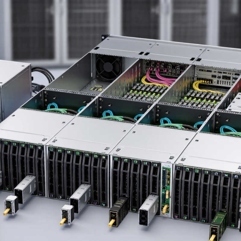
Choosing a chassis backplane starts with the slot map. Count occupied slots, reserved spares, and any modules that need adjacent space for airflow or cabling. Then calculate power per slot, including peak draw during startup—not just typical operation. Add a practical reserve for future cards and cooling. This margin is a design choice, not a universal rule; validate it against the chassis power supplies and thermal limits. Uptime Institute’s 2024 Global Data Center Survey found that 45% of operators saw power availability as an obstacle to expanding IT capacity. That makes a realistic power budget more than a spreadsheet exercise.
For data rates, specify the required link speed at each slot. IEEE 802.3 defines 25GbE and 100GbE standards; many 100GbE implementations use four 25-Gb/s lanes. Check that the backplane, connectors, and board traces support the intended signaling rate and lane configuration. The Ethernet Alliance’s 2024 Ethernet Roadmap tracks advances through 800GbE and 1.6TbE, a reminder that today’s requirements may not fit tomorrow’s modules. Verify signal integrity with the actual card and cable configuration. A speed label alone is not enough.
Tips: Build a slot-by-slot table listing card type, peak watts, lane rate, and cooling needs. Leave room for growth, but challenge every assumption; unused capacity still costs power and space.
Choosing a chassis backplane starts with the data each slot must carry. PCIe 5.0 runs at 32 GT/s per lane, making it a practical fit for many accelerators, storage devices, and network cards. Its mature ecosystem can simplify integration. Still, the headline rate is not usable application bandwidth; encoding, topology, and traffic patterns affect real throughput. Check the backplane layout and cable or connector limits before relying on a specification sheet. Details matter.
PCIe 6.0 doubles the signaling rate to 64 GT/s per lane. It uses PAM4 signaling and FLIT-based data handling with error correction, so the backplane and endpoints must support the full design. That speed can benefit dense, high-throughput systems, but it may add cost and signal-integrity demands. Measure the actual workload. VPX is different: it is a rugged modular architecture with multiple backplane fabric options, rather than one fixed data rate. It suits embedded systems where shock, cooling, service access, and long-term module compatibility matter. A fast fabric is not always the best choice. Compare required lane counts, power, airflow, and upgrade plans, then test with the intended cards installed; specifications alone can leave gaps.
Compare PCIe 5.0 and PCIe 6.0 signaling rates, and understand why VPX has no single fixed rate.
VPX is profile-dependent: VPX defines a modular card-and-backplane architecture, not one universal signaling rate. The backplane’s fabric, selected standard or profile, lane count, and components determine its data rate. PCIe figures shown are raw signaling rates per lane, not application throughput.
Choosing a chassis backplane starts with signal integrity, not only mechanical fit. A polished backplane can still create serious data errors.
Measure insertion loss across the intended frequency range. Excessive loss reduces the receiver’s eye opening and limits usable channel length. Use a vector network analyzer with calibrated fixtures whenever possible. Cable quality and fixture removal matter. Poor calibration can make a good backplane appear weak.
Crosstalk deserves equal attention. Dense routing, long parallel traces, and careless via fields can couple unwanted energy into neighboring pairs. Check both near-end and far-end crosstalk under realistic module loading. I have seen clean laboratory results change after adding connectors, cards, and metalwork. The complete channel matters more than the bare board.
Target differential impedance between 85 and 100 ohms, according to the system requirement. Confirm it with TDR measurements and stackup calculations. Trace width, dielectric thickness, copper roughness, and connector geometry all influence the result. Keep differential pairs symmetrical, preserve their return paths, and remove unnecessary via stubs. Small discontinuities accumulate.
Do not trust one test condition. Temperature, manufacturing tolerance, and assembly pressure can shift performance. A backplane that passes at one frequency may struggle at another. Recheck the design after fabrication, because simulation is useful but never perfect. Sometimes the overlooked connector transition is the real problem.
Choosing the right chassis backplane starts with mechanical compatibility, not slot count. In field integration work, I measure board height, depth, connector position, and guide-rail spacing before comparing specifications. A backplane can fit the rack and still reject a module. That mistake is expensive. PICMG platforms often suit structured, modular systems, but the exact revision matters. Check keying, alignment, and rear-transition support against the target boards.
CompactPCI Serial and VPX use different mechanical and electrical ecosystems. Their connectors, pin assignments, cooling paths, and module retention methods are not interchangeable. Confirm the required 3U or 6U format separately. 3U saves space and weight, while 6U provides more board area and expansion room. Neither choice is automatically stronger. I have seen a compact enclosure fail because a tall heat sink blocked the adjacent slot. Leave room for airflow, cabling, and service access.
Read the backplane drawing, not only the product summary. Verify slot pitch, board insertion depth, mounting holes, guide rails, and allowable tolerances. Ask whether the chassis supports front-to-rear or side-to-side airflow. Also inspect power-entry clearance and grounding provisions. Standards improve confidence, but they do not remove integration risk. My own checks are not perfect; early measurements can miss cable bend radius or latch travel. A physical mock-up exposes those errors before production. Record every interface and test one populated slot before approving the full chassis.
How to Choose the Right Chassis Backplane
Thermal limits often decide whether a chassis backplane remains reliable after installation. ASHRAE TC 9.9 recommends 18–27°C inlet air for common data-center equipment classes. Measure inlet temperature at the backplane, not only at the room sensor. A 1U chassis usually has little vertical space for airflow. Its compact fans can create sharp pressure drops across dense connectors. A 6U chassis offers more room, but a larger enclosure does not automatically improve cooling.
Check the airflow path with a loaded configuration. Measure temperature before and after sustained operation, especially near power connectors and high-speed transceivers. The Uptime Institute’s Global Data Center Survey repeatedly identifies power and cooling capacity as major operational concerns. That finding matters at the rack level. A backplane may pass a short laboratory test, then exceed limits when every slot is populated. Thermal simulation helps, but physical testing remains necessary.
Compliance requires more than a familiar voltage rating. IEC 62368-1 uses hazard-based safety engineering for audio, video, information, and communication technology equipment. Confirm insulation, creepage, clearance, accessible temperature, and protective bonding requirements. Document the exact chassis height, airflow direction, ambient temperature, and installed modules. These details are easy to overlook. I would not trust a generic “1U to 6U compatible” claim without test conditions. Recheck it.
| Chassis Size | Approx. Height | Typical Backplane Application | Recommended Airflow Direction | Typical Cooling Design Target | Common Thermal Risk | Backplane and Slot Considerations | IEC Compliance Check | Selection Guidance |
|---|---|---|---|---|---|---|---|---|
| 1U | 44.45 mm | Compact embedded control, networking, monitoring, and low-profile compute systems | Front-to-rear airflow is commonly preferred for rack installation | Usually designed for approximately 150–350 W of total system heat, depending on fan capacity and inlet temperature | High Very limited vertical clearance and small heatsinks can create high component temperatures |
Use a low-profile backplane with careful connector placement; reserve airflow paths above high-power processors, power converters, and storage devices | Evaluate the complete end product against IEC 62368-1; check accessible energy, fire enclosure, insulation, bonding, and protective earthing requirements | Choose only when total power, card height, cabling, and service access are tightly controlled |
| 2U | 88.90 mm | General-purpose industrial systems, storage appliances, and moderate-density embedded platforms | Front-to-rear airflow with separate paths for processors, power supplies, and expansion cards | Approximately 300–700 W is a common planning range for a well-ventilated system | Medium–High Uneven airflow distribution may leave rear cards or power sections above their rated temperature |
Provides more room for airflow guides and standard-height cards; verify slot pitch, card retention, and rear I/O clearance | IEC 62368-1 assessment normally applies to the finished equipment; verify power-entry protection, touch-current limits, and enclosure openings | A practical compromise when 1U is too thermally constrained but a taller chassis is unnecessary |
| 3U | 133.35 mm | Industrial automation, telecom control, instrumentation, and higher-power modular systems | Front-to-rear or bottom-to-top airflow; use baffles to prevent recirculation | Approximately 500–1,000 W may be achievable with adequate fan pressure and unrestricted vents | Medium Thermal gradients can develop between densely populated plug-in cards |
Supports taller card assemblies and more generous cable routing; verify backplane connector insertion force and card guide alignment | Check protective earth continuity, reinforced or basic insulation where applicable, fire enclosure materials, and abnormal-operation behavior under IEC 62368-1 | Suitable for modular designs that require more cooling area and mechanical serviceability |
| 4U | 177.80 mm | High-capacity industrial computers, instrumentation, storage, and multi-board processing systems | Front-to-rear airflow is common; vertical airflow may be used when card orientation and heat-rise effects are controlled | Approximately 700–1,500 W can be considered for planning, subject to fan, filter, and ambient-temperature limits | Medium Large internal volume can permit bypass airflow around cards if blanking panels are omitted |
Allows full-height airflow guides, larger fans, and improved cable management; install filler panels in unused slots to maintain pressure balance | Confirm the chassis does not compromise the final equipment’s IEC 62368-1 fire, mechanical, electrical, and accessibility requirements | Good fit for systems needing substantial expansion capacity without using a floor-standing enclosure |
| 5U | 222.25 mm | Large modular compute, laboratory instrumentation, industrial control, and mixed active/passive card systems | Front-to-rear, side-to-side, or bottom-to-top airflow may be used; airflow zoning is strongly recommended | Approximately 900–2,000 W is a possible design range with sufficient fan volume and heat-removal margin | Medium Fan redundancy, filter loading, and hot spots around power conversion hardware require validation |
Provides space for multiple backplanes, redundant fans, and service loops; verify that backplane segmentation does not obstruct cooling channels | Assess the complete assembly under IEC 62368-1, including multiple power sources, stored energy, protective bonding, and fire containment | Choose when high expansion, redundant cooling, and frequent maintenance are more important than minimum rack height |
| 6U | 266.70 mm | High-density modular platforms, communications equipment, defense or laboratory systems, and multi-zone backplane architectures | Use defined airflow zones with front-to-rear or bottom-to-top paths; avoid mixing hot exhaust with adjacent card inlets | Approximately 1,200–3,000 W may be feasible, but the actual limit depends heavily on ambient temperature and cooling architecture | High at High Power Large systems can conceal recirculation, pressure drop, and localized thermal runaway |
Suitable for separated power, processing, and I/O backplanes; validate connector derating, card extraction force, structural rigidity, and fan-failure behavior | IEC 62368-1 verification should cover the integrated system, including hazardous-energy sources, enclosure openings, flame-rated materials, earthing, and single-fault conditions | Best for high-capacity designs where thermal zoning, redundancy, and physical access justify the larger enclosure |
| All sizes | Rack height is measured in U; 1U equals 44.45 mm | Any system using a passive or active backplane | Maintain a clear inlet-to-exhaust path and prevent exhaust air from returning to the inlet | Use component data sheets, measured pressure drop, fan curves, and worst-case ambient temperature rather than chassis height alone | Validate Filter blockage, fan aging, cable obstruction, and partially populated slots can change the thermal result |
Check card spacing, connector temperature rating, copper current capacity, creepage, clearance, grounding strategy, and mechanical retention | IEC 62368-1 is a product-safety standard for audio/video, information, and communication technology equipment; the applicable edition and national deviations must be confirmed for the target market | Request thermal test evidence at the specified ambient, voltage, load, airflow restriction, and fan-failure conditions before finalizing the chassis |
Map every slot, including occupied positions, spare spaces, and modules needing adjacent airflow or cable clearance. A spreadsheet can lie. List card type, peak watts, lane rate, and cooling needs for each slot.
Calculate peak startup power, not only normal operating power. Add practical capacity for future cards and cooling, then verify it against supply and thermal limits. There is no universal reserve percentage. My estimate may still be wrong.
Specify the required rate for every slot, such as 25GbE or 100GbE. A 100GbE connection may use four 25-Gb/s lanes. Check connectors, traces, lane configuration, and actual card-and-cable combinations.
No. A faster interface can increase cost, heat, and signal-integrity demands. A 32 GT/s bus may suit common accelerators, storage devices, and network cards. A 64 GT/s PAM4 design can support denser traffic but needs stronger validation. Fast is not always practical.
The headline rate is not application bandwidth. Encoding, topology, error correction, lane count, and traffic patterns affect usable throughput. Test the intended workload with installed cards. Specifications leave gaps.
Measure board height, depth, connector position, guide-rail spacing, and insertion depth. Check slot pitch, mounting holes, keying, alignment, and rear-transition support. A chassis can fit the rack and still reject a module.
A 3U format saves space and weight. A 6U format offers more board area and expansion room. Neither is automatically stronger. Check heat-sink height, cable paths, airflow, and service access before deciding.
Confirm front-to-rear or side-to-side airflow, power-entry clearance, grounding, and cable bend radius. A tall heat sink may block the next slot. A latch may not travel fully. Use a physical mock-up and test one populated slot before full approval.
Leave room for additional cards, higher lane rates, cooling, and service access. Challenge every unused-capacity assumption because empty space still consumes money and enclosure volume. Record each interface and test upgrade plans with the actual cards installed.
Choosing the right chassis backplane begins with defining the system’s practical requirements. Determine the number of slots, total power budget, and expected data rates, especially when supporting 25–100GbE traffic. Compare suitable bus architectures, including PCIe 5.0 at 32 GT/s, PCIe 6.0 at 64 GT/s, and VPX, while considering bandwidth, latency, scalability, and future upgrade needs.
Signal integrity should be verified through insertion-loss and crosstalk analysis, with differential impedance controlled within the required 85–100Ω range. Mechanical compatibility is equally important, including support for established modular standards, serial backplane designs, VPX configurations, and 3U or 6U form factors. Finally, confirm thermal and compliance limits by evaluating airflow, enclosure sizes from 1U to 6U, cooling capacity, and applicable IEC safety ratings. A balanced assessment of electrical, mechanical, thermal, and regulatory factors will help ensure reliable operation and long-term system flexibility.
